








 Contact Platform Support
 Help Center
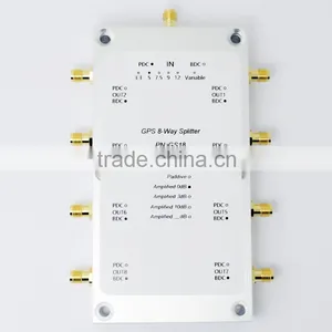
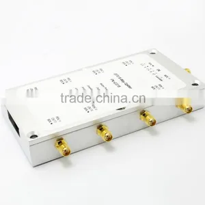
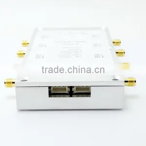
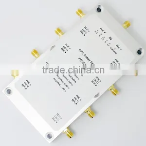
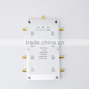
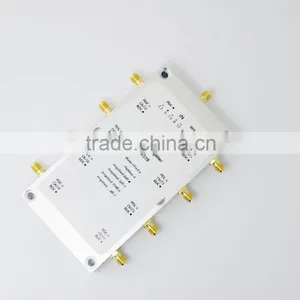
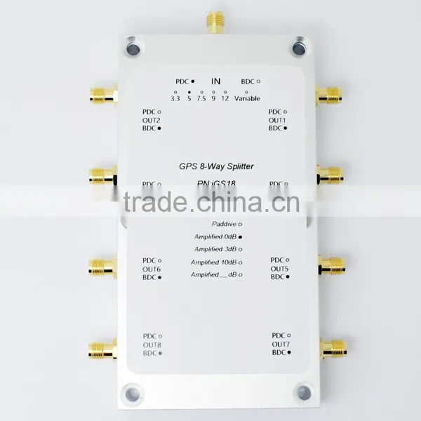
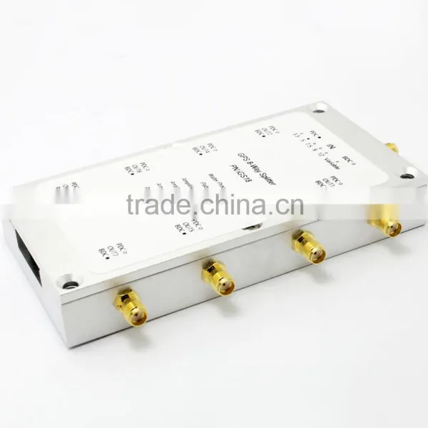
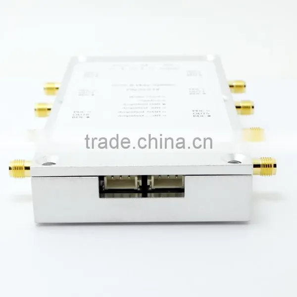
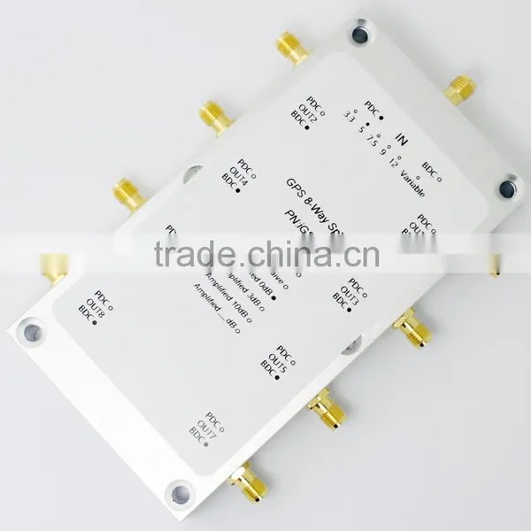
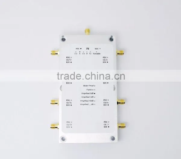
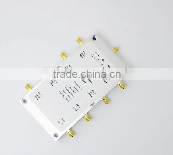
GPS Splitter 8 Way GPS Power Splitter IGS18

Related Products
-
 Dual Antennas Input Gain Control 8 Way GPS SplitterUS$ 1 - 1,200MOQ: 1 Piece
 -
2 Way GPS Power Splitter GPS SplittersUS$ 1 - 148MOQ: 1 Piece
-
Multi-channel Port 4 Way GPS SplittersUS$ 1 - 280MOQ: 1 Piece
-
8 Way GPS Power Splitter GPS SplittersUS$ 1 - 380MOQ: 1 Piece
-
Power Splitter 4 Way GPS SplittersUS$ 1 - 338MOQ: 1 Piece
Description
iGS18 Characteristic
Specifications
Operation instructions
Pin definition:
1 +12 V; 2 GND; 3 RXD;
4 +12 V; 5 GND; 6 TXD
Note: RXD product iGS18 serial port connector TXD; product TXD connected to the serial port connector RXD.
2. Serial port parameters
Open serial debug assistant software:
Serial number view:
Right‐click on "My Computer", select "Manage" Double‐click "Device Manager" and double‐click can see the connection port serial number is COM4.
NOTE: You must insert the serial connector can see the serial num.
3. Calculation of power off and read voltage instructions
Instruction consists of 8 hexadecimal format.
STX: 0x02 frame start flag;
DLE: 0x10 transcoding, for use in the frame start or frame end flag before, if DLE equal to the value data appears in the frame, the data retransmission protocol requires one to represent distinction,that is represented by two consecutive DLE data, a DLE represents the transcoding;
CMD: Communication instruction data type, including data communication instruction (0xF1) and control commands (0xF2) of two types;
Parameter: CMD communication instruction data content, data length;
ETX: 0x03 frame terminator flag (not included in the back of the validation data);
BCCL: binary BCC check code low 8;
BCCH: binary BCC code high 8.
Then DLE, STX and ETX three hexadecimal constant, which is the first 1,2,5,6 These four numbers are the same, you need to calculate the CMD, parameters, BCCH and BCCL four hexadecimal number.
Basic power off instruction:
Schematic diagram of serial connection:
Mechanical
GEMS RF&MICROWAVE and GEMS NAVIGATION was established in 2007, professionally designs, products and sales of coaxial microwave devices and equipment. GPS indoor coverage systems and accessories, high-power coaxial attenuators, high-power coaxial load, we accumulated many years of designing and manufacturing experience, our own designed and product of GPS indoor coverage systems and related GPS power splitter and amplifier, GPS antenna and other products widely used in microwave communications, mobile communications, high-precision measurement, power, research institutions, colleges and universities, manufacturing and other fields.
Contact:
Tel:(86)755-29644311 ext 803
Fax:(86)755-29644383
Sales QQ:1762007014
Purchase QQ:1523055690
Add: 301, HuaChuangDa Building, CuiZhu Road, 46 Baoan District, Shenzhen, China
All products have been strictly inspected, all are qualified products.
We promise one‐year guaranty and 5‐year available.
Under warranty, products gone wrong which be identified not be human factor, can be replaced free or repaired.

Send Inquiry to This Supplier

You May Also Like
-
Clean Room TelephoneUS$ 140 - 160MOQ: 1 Piece
-
Hot Sale Hdpe 40/33 Pipe for Fiber Optic CableUS$ 0.63 - 0.98MOQ: 30000 Meters
-
S42024-L5101-A120-02 Control Rectifier Switch Service BoardUS$ 100 - 3,000MOQ: 1 Piece
-
FC-FC Fiber Optic Patch CordUS$ 1.12 - 2.6MOQ: 10 Pieces
-
Anritsu Site Master S331L PROMOTION PriceNegotiableMOQ: 1 Set
-
Strong Controllability 1310 Nm/1550 nm Wavelength FTTH Optical Receiver With Double WavelengthUS$ 10 - 50MOQ: 1 Set
-
Just for You Fiber Optics Light Up Paper Bag Vase, Paper Flower VaseNegotiableMOQ: 5000 Pieces
-
CYLINDRICAL MUTINATION PLUGSNegotiableMOQ: 1
-
USB AF-MINI USB 5P-B M Adapter VK2-0055NegotiableMOQ: 5000 Pieces
-
25.6V20Ah LiFePO4 for Communication DevicesNegotiableMOQ: 50 Packs


