
Air Circuit Breakers (ACBs) are one of the most fundamental parts of modern technological systems, defending circuits from overcurrents, short circuits, and other faults. Their reliability and functionality, however, are concerned with maintenance. Without regular servicing, ACBs face issues that can expose a system to performance degradation, increased failure, or safety risks. These ACB maintenance tips are simple yet practical and oriented toward maintaining safety and reliability. If you are a facility manager, technician, or an electrical system user, these suggestions will protect your equipment from being dangerous and unreliable due to neglecting maintenance.” Watch this video to learn how to ensure your air circuit breakers operate at peak efficiency. Click here to read more!
What is an Air Circuit Breaker, and Why is Proper Maintenance Important?
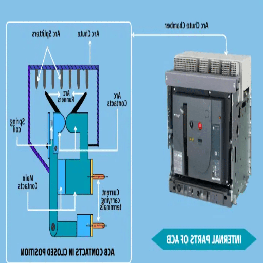
The Role of an Air Circuit Breaker in Electrical Systems
Due to an ACB’s functionality and operation, an Air Circuit Breaker is regarded as a fundamental component of a modern electrical distribution system. It enhances the operational safety and reliability of services while ensuring efficiency in power supply management. Altogether, an ACB is a device that disables electrical power to a section of the circuit whenever an error could produce an overload, short circuit condition, or abnormal voltage ion variation. ACB aims to control and avert possible dangers that can lead to equipment impairment, increased risks of fires, or long service delays.
ACBs utilize air as the primary medium for arc extinction during the disconnection process. This feature works exceptionally well for high-current applications in industrial plants, most commercial buildings, and power generation plants. ACB’s power and efficiency ensure the protection of critical systems by managing large short-circuited currents through steadfast construction.
Current ACB include additional features such as adjustable trip settings, remote communication, and remote checking capabilities. These improvements allow for more excellent fault analysis, better verification, and more formidable integration into modern protective devices and innovative grid systems. ACBs that are not over-maintained improve a system’s dependability while simultaneously reducing expenses incurred from unscheduled operational downtimes, equipment failures, and accidents. In order to optimize the performance and safety of any electrical system, equipment operators need to understand the mechanisms and active maintenance system properly.
How Air Breakers Protect Equipment from Short Circuit Damage
Air circuit breakers are one of the most effective ways of protecting equipment against short circuit failure modes and damages. Short circuit faults are the most critical risk for overcurrent, with the main danger being excessive parts heating. Air breakers cut off the supply of current using the specialized arc extinguishing method contained in the air-insulated chamber. The breaker senses the incorrect value of current using several sensors and ascertains the contact closure, forming a circuit. This arc cools rapidly in the chamber, allowing for circuit protection.
Like modern circuit breakers, ACBs have refined protection features such as adjustable trip settings and limiters for fault current. These features allow ACBs to accurately tune to various fault conditions while mitigating interruptions to the integrated systems as much as possible. ACBs prevent long downtimes by detaching only the affected portions of the network, a condition that also reduces extensive damage risks. They are crucial in industrial, commercial, and renewable energy applications due to high fault currents, detailed diagnostic data, and reliability, safety, and risk mitigation.
The Consequences of Enhanced ACB Maintenance on System Downtime Mitigation
Air circuit breakers (ACBs) need proper routine maintenance to sustain infrastructure reliability and safety continuously. Periodic cleaning and testing and basic inspections on ACB parts tremendously impact the chances of unforeseen equipment failures that lead to downtime. An internal study A reliance on preventative maintenance. Such practices enable an extended life span of around 20% for circuit breakers, a smart expense for industries that depend heavily on a steady power supply.
One of the most crucial aspects of ACB maintenance is the periodical verification of their tripping mechanisms and calibration. Ensuring this system works optimally is vital for effectively handling fault currents and protecting the network and personnel from electrical accidents. Moreover, comprehensive concentration scrubbing of contacts and checking for wear helps ensure reliable conductivity. In contrast, early detection of any mechanical wear and tear minimizes chronic failure risks over time. The addition of modern diagnostic tools, such as thermal imaging or online monitoring systems, enables technicians to address obfuscated issues in advance, further improving the dependability and safety of the entire electrical infrastructure.
ABCs in industrial plants, data centers, and renewable energy grids are critical. Therefore, using structured maintenance approaches together with advanced methods of analysis yields the most effective results. This not only reduces service interruption but also helps ensure the long-term efficiency of the infrastructure while maintaining excellence in operations.
What Are the Essential Maintenance Procedures for Air Circuit Breakers?
Checking For Wear and Damage on Arc Chutes and Contact Points
Contact points and arc chutes are two key components of an air circuit breaker (ACB), and its contact points risk losing performance capabilities due to wear and tear. With high-energy arcs, contact points possess a risk of endless thermal heating, which escalates the risk of damage and overheating.
During an ACB’s operation phase, the contact points must be maintained for heat deposition, potential thermal damage, erosion, and discoloration, as these factors determine electrical performance. If any of the above-stated factors are observed, replacing the components at once is essential. Physical damage, carbon blockages, build-up, and residue need evaluation, along with proper sanitation methods, for maximum equipment efficacy.
A defined maintenance handout that sets a schedule for maintenance routines could ensure smooth operation under these specified conditions. This directly translates to increased machine operating time while simultaneously reducing maintenance costs.
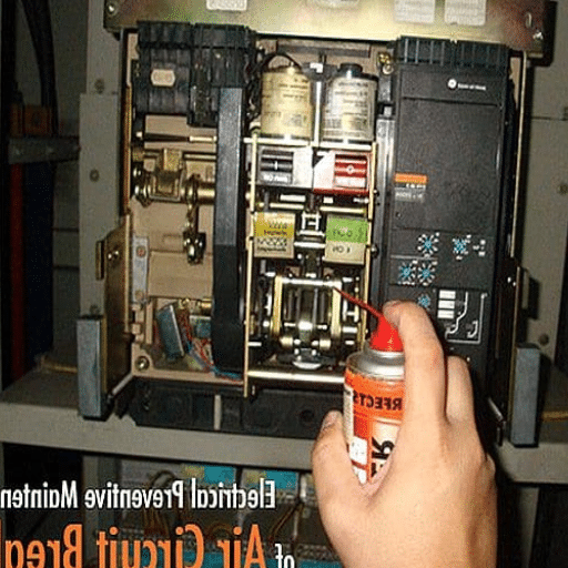
Cleaning and Lubricating Moving Parts to Ensure Most Optimal Operation
The machinery’s effectiveness and dependability greatly rely on the condition of its moving parts. With time, friction, heating, and wear can occur on moving parts as dust, dirt, and other debris can build up. Regular cleaning is necessary to restore functionality to such components. Utilize proper equipment such as brushes, compressed air, or even soft, dry cloths to clean delicate system parts that have the potential to become damaged or worn.
After components have been cleaned, lubrication must also be applied to minimize friction and avoid impediments to functioning smoothly. Selecting adequate lubricant is also critical for the equipment manufacturer’s guidance regarding operating conditions (heating and wear) of construction materials. Systems should only be lubricated with a precise quantity so as not to draw additional dirt or even cause excess lubricant. Routine observations of lubricated parts ensure components are damage-free and aid in detecting unwanted wear and overload damage.
Crucial attention to detail while conducting cleaning specific to each system, aided with the appropriate looser, aids machine operators in boosting efficiency, reducing energy expenditure, and further increasing other vital machine parameters alongside the overall lifespan of the machinery.
Testing Examination of Functions of Circuit Breakers and Relay Settings
Testing circuit breakers with their associated trip procedures and relay settings helps verify the dependability and safety of electrical systems. Circuit breakers are essential in protecting electrical circuits from overloads or faults. Their trip mechanisms should be well-adjusted in overwhelming situations. Similarly, predetermined limits activate protective relays and serve as an essential protection device. They disconnect equipment that could cause additional damage, reducing potential outages.
The latest testing procedures include sophisticated feedback instruments that emulate fault situations, enabling a comprehensive assessment of both relay and breaker operations. Major parameters such as time delay intervals, current level setting, and device interrelation should be checked for compliance with system expectations and governing policies. By completing these tests, organizations can mitigate challenges like contact resistance, mechanical attrition, or incorrect relay configurations before they develop into critical issues.
In addition, relay logic enhancement results in effective discrimination, thereby obviating unwarranted power disruptions. These tests, together with a robust maintenance plan that incorporates predictive maintenance, strengthen system fortitude, enhance uptime, and prolong equipment life. Periodical testing also guarantees adherence to industrial standards while supplying essential benchmark information.
How Often Should Air Circuit Breaker Maintenance Be Performed?
Recommended Maintenance Schedules Based on Voltage and Current Ratings
The air circuit breaker maintenance frequency is determined by the following: voltage class, current ratings, environmental conditions, and operational demands. For low-voltage air circuit breakers, routine inspections and minor maintenance should generally be done every 12 – 18 months, with a detailed overhaul coming every 3 to 5 years. Medium voltage breakers will likely need to be assessed more frequently in high-load or critical applications. They should be inspected every 6 – 12 months, with comprehensive servicing every 2-3 years.
Given the greater stress levels and importance of high-ohm breakers in grid stability, these will often follow stricter schedules. For them, regular condition monitoring (thermal imaging and contact resistance testing) should occur semi-annually, with complete maintenance checks every 2-3 years. Breakers working under harsher conditions, such as extreme temperatures and high humidity, will likely need to change these timelines due to increased environmental wear and tear. Sticking to these timelines will ensure the optimal efficiency of the breakers in safeguarding the electrical infrastructure.
Signs That Indicate An Air Breaker Needs Your Attention
Warning signals for air breaker issues should always be recognized to keep your electrical system safe and will aid in the prevention of expensive damage to your equipment. Air breakers require immediate attention when there is frequent tripping without clear reasons, a pungent cigarette-type odor near the breaker, or even discoloration, corrosion, or damage to the casing. A breaker in distress can also make strange noises, such as buzzing and crackling, indicating the presence of electrical faults or internal damage.
Not noticing the generation of unusual heat around the breaker or its area accompanied by a failure of the above conditions can potentially indicate a malfunction. These conditions demand serious inspection and repair. Being swift in your progress will ensure risk mitigation, reliable performance, and longevity of the systems attached to the air breaker. Additionally, unorthodox heating with poor connections can lead to overloading.
What Tools and Equipment Are Needed for Air Circuit Breaker Maintenance?

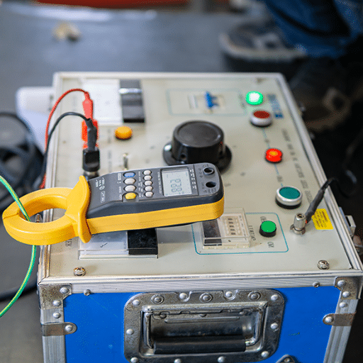
Critical Testing Tools for Evaluating Electrical Parameters and Performance
Effective air circuit breaker maintenance must be done with a specific set of tools and equipment to ensure an accurate assessment of electrical parameters and optimal performance. Primary testing tools include:
Insulation Resistance Testers: These devices check the integrity of the insulation on the breaker to avoid electrical failures or leaks.
Primary Current Injection Test Sets: These testers are designed to confirm that a breaker can operate under extreme currents and assess its trip function under simulated real-life operating conditions.
Contact Resistance Testers: Often referred to as cross-breaker contact resistance testers, these measure the contacts of the circuit breaker, thus helping to monitor them for any wear or degradation that may affect performance.
Thermal Imaging Cameras: With these devices, technicians can find hotspots caused by faulty connections, overloaded components, or internal failures without having to come in direct contact with the devices.
Voltage Testers and Multimeters are crucial for confirming that the correct voltage, electrical flow, and continuity are achieved so that the breaker is within specified ranges.
Timing Analyzers: These devices measure the breaker’s tripping and closing times to ensure that they adhere to manufacturer standards regarding delays during critical moments.
Dynamic Micro Ohm Testers: These devices confirm that there is no excessive power loss during operations by assessing the condition of the contacts while on load.
With the help of this advanced equipment, including tools that analyze the breaker’s performance, maintenance personnel can identify issues much earlier than usual while still upholding strict safety standards.
Safety Equipment Required When Working with High Voltage Circuit Breakers
Working with high-voltage circuit breakers involves significant risk, making using and selecting appropriate safety tools critical to uphold personnel and industry safety standards. Some of the high-voltage tools include:
Dielectric Safety Boots: These boots effectively insulate the high voltage, protecting the user from electric grounding through the feet. In addition, slip-resistant soles enhance the user’s stability in a number of working conditions.
Face Shields and Safety Goggles: The shields must be capable of offering protection from UV rays resulting from prolonged exposure to electric arcs. The goggles ensure safety for an individual’s eyes, while the shield acts as a cover for the face against sparks, flashes, or debris that may result from an operation or a malfunction.
Single-Use Plastic Protective Clothing: This type of clothing acts as a safety measure against dirt exposure that might occur when a wearer engages in work activities for a lengthy period.
Arc Flash Suits: These thermal suits protect workers against burns from possible arc flash occurrences. They are made of fire-resistant materials and enclose helmets, gloves, jackets, and overalls that can endure specific energy levels.
Voltmeter: Voltmeters ensure equipment is dead prior to starting work, preventing accidental contact with energized components. The tools also enable personnel to determine whether equipment is live or not.
Respiratory Protection: In the vents where possible exposure to airborne contaminants is suspected, circulatory clothing that can protect from such hazards is essential.
All safety tools should pass tests measuring their operational effectiveness, be inspected frequently, and work at peak performance. Taking a holistic stance on personal protective equipment (PPE) encourages more excellent workplace safety to risks associated with high-voltage environments.
How do you troubleshoot common air circuit breaker problems?
Troubleshooting Draw-Out Mechanism Problems
Diagnosing problems involving the draw-out mechanisms of air circuit breakers begins with a visual inspection. The first assurance is the mechanism’s absence of signs of wear, damage, or misalignment. Obstruction to smooth operation is often a result of loose parts, excessive dirt, or debris. Thus, I check that all components are clean and in their respective positions. Provided the mechanism appears physically intact, my steps proceed to check lubrication. Without sufficient or dried grease, the operational movement could be an issue; thus, the seamless movement calls for dire lubrication. This requires the use of recommended lubricants specific to the manufacturer’s guidelines.
Focusing on the mechanical interlocks and their connections is my next step. Verification of the correctness of interlocks is checked with the movement alignment examination of the stationary and moving contacts. Aligned contacts could fail the engagement or disengagement of the circuit breaker, thus, operational failure. With precise measurement tools, I check if set tolerances are met, ensuring that clearances allow adjustments and that realignments are done. At this stage, I check whether the obstruction-free movement of the mechanism occurs between the withdrawn, test, and connected positions.
I conduct functional testing of the equipment on the circuit breaker in the “test” position. This verifies that the draw-out mechanism performs correctly under simulation tests and before full integration with the system. During these checks, I pay attention to any abnormalities, including excessive or restrictive resistance and strange sounds while the equipment runs. If the problem is not resolved, I could refer to the technical documentation of the specific model breaker and discuss it with some expert technicians if necessary. I take it upon myself to confirm that the draw-out mechanism is operable to safeguard the dependability and safety of the whole electrical system.
Fixing Issues with Arc Extinguishing Systems
My initial concern when dealing with issues regarding arc extinguishing systems focuses on the availability of safety measures to avoid any harmful conditions that might occur. For preventive measures, I first check for any electrical hazards by isolating the system and investigating each component of the arc extinguishing system for obvious signs of damage or unhealthy conditions. This involves assessing the status of the arc chutes, barriers, and contacts to determine any superficial faults that affect the functionality of the system.
When the problem is not apparent, I first investigate the system under controlled conditions. Using my tools, I check voltages, response times, and insulation resistance, among other parameters, to verify that each component works correctly. Even during basic testing, I find problems like insufficient insulation or misalignment that would otherwise go unnoticed. If I see something unusual, I cross-reference the manufacturer’s technical documentation for troubleshooting procedures and recommended actions.
If the issue is more complicated or persistent, I usually reach out to other more advanced technicians or engineers who have worked with arc extinguishing systems. We can analyze the system’s design and operation history as a team to find root causes. This type of thorough problem-solving provides a solution to the problem at hand and removes the potential for future occurrences by reinforcing foundational weaknesses within the configuration. Following these steps, I can restore the system’s operational capacity with maximum reliability and safety to the entire electrical network while ensuring performance above standards.
How to Solve Contact Separation and Magnetic Blowout Failures
My first approach to dealing with contact separation and magnetic blowout failures would be to thoroughly examine the contactors and the blowout coils in the arc extinguishing system. This step includes looking for any signs of wear, misalignment, or damage that could inhibit movement. Worn or contaminated surfaces will increase resistance and prevent separation. At the same time, problems with blowout coils, such as short-circuiting and broken connections, would diminish their ability to form the required magnetic field. Recognizing these defects provides the opportunity to take corrective actions such as repairing, replacing, or realigning these components to restore functionality.
Afterward, I will inspect the operational working conditions of the system in question to ensure they conform to the manufacturer’s guidelines. Under or improper voltage levels, imbalances, miscalibrated currents, and contact overloading are some parameters that could worsen wear and lead to poor performance of the blowout coils. Assessing these conditions through monitoring and testing enables determining if extensive or any changes need to be made for improved functional optimization. Moreover, many parts, such as moving components in the contact’s mechanism, are easier to adjust, with tensioning, proper calibration, and lubrication boosting reliability.
Lastly, I would adopt a proactive strategy by instituting preventive maintenance procedures to reduce future failures. This could involve regular checking intervals, thermal imaging for early overheating detection, and teaching staff overheating work malfunctions. Employing condition monitoring systems that track the wear on contacts and the integrity of the coil windings provides insight into intervention requirements, enabling accurate predictions. The right combination of advanced and automated monitoring, optimizing system performance, and preventive measures will increase these systems’ reliability while resolving the issues.
Frequently Asked Questions (FAQs)
Q: How often is electrical maintenance conducted on-air breakers employed in industrial processes?
A: When it comes to industrial applications, air breakers need periodic inspection and cleaning of contacts, inspection of arc chute wear, and the checking of mechanical operations. Maintenance must include checking that control circuits operate correctly, inspecting the magnetic field parts, and ensuring all joints are made adequately without any looseness. In some cases, attention may be necessary to the cooler components of the unit, for example, with 4000 amp breakers. Routinely checking that the trip functions operate correctly helps lubricate moving parts, avoiding unscheduled failures in IDC switchgear systems in critical industrial operations. Switching devices must be reliable if the system is to remain efficient.
Q: How is the arc extinguishing system implemented in air blast circuit breakers?
A: In the case of air blast circuit breakers, separated contacts are accompanied by a fresh delivery of compressed air into nozzles directed to the arc area. This compressed air serves to blow the arc away from the contacts. The force of the compressed air serves not only to cool the arc but to elongate it. The system is supplemented by blowout coils which further assist the arc into the arc chute. This technology excels in high voltage settings, including 15 kV substations, where the need for instantaneous blowing of the arc is critical for the integrity of the electrical components and overall system reliability.
Q: What advantages do air circuit breakers have over oil circuit breakers?
A: Air circuit breakers provide various advantages over oil circuit breakers. The presence of oil in circuit breakers poses a fire risk; therefore, air circuit breakers are safer. Also, there is no oil to check or replace, so they require less maintenance. Furthermore, they are safer for the environment. In particular, DC applications interrupt fault currents much more swiftly and efficiently than oil circuit breakers. Westinghouse and Eaton air breakers do not emit harmful gases, making them suitable for indoor installations. They are also commonly more compact, which is better for modern switchgear applications with space limitations. Air circuit breakers also provide more reliable protection against short-circuit conditions in industrial control systems.
Q: How often should air breakers be inspected for high-voltage use?
A: For air breakers in high voltage applications, such as 15 kV substations, it’s critical to do a detailed inspection at least once a year and visual inspections quarterly. Some breakers operating frequently or working in especially harsh conditions may require frequent inspections. Other inspections need to confirm the condition of the arc chute and contact wear and check blowout coils and mechanical and electrical controls. For 3-pole breakers with more critical loads, proactively test the trip mechanism more often. Transformer protection breakers must receive these special inspections to interrupt potential short-circuit currents without damaging expensive electrical components.
Q: What must be physically checked when an air breaker does not operate as intended?
A: As a troubleshooting procedure for the mechanical issues with air breakers that do not operate electrically, start by confirming that the control circuit is powered and fuses are intact. Measure the voltage in both trip and close coils and ensure the electrical power in those components is active. Check all connections to see that they are correctly tight and secured. Inspect the mechanical linkages for binding and worn parts, which might hamper proper movement. Also, check the auxiliary contacts and limit switches that could obstruct electrical activation. For breakers controlled by DC, check if the polarity used is correct. If the breaker contains electronic trip devices, ensure that there are no error messages or indications that problem states are active. If the environment applies to heavy-duty operations, verify the alignment and functioning of the magnetic hammers and the field.
Q: What type of safety concerns are present for the maintenance of air circuit breakers?
A: For air circuit breakers, maintenance must begin with completely de-energizing and isolating the breaker alongside applying appropriate lockout/tagout procedures. The absence of voltage must be verified using appropriately rated test equipment. Any stored energy within springs or capacitors should be discharged before beginning work. Potential arc flash lies with the work performed, so appropriate PPE must be worn. A sufficient cooling-off period before handling must be observed when dealing with high-amp breakers such as 4000 amp units. Specific safety documents should be adhered to with equipment from Westinghouse or Eaton. Modification of the safety features, as well as bypassing interlocks, must never be done. Always follow established electrical safety standards to avoid accidents when working on the control components.
Q: How does the external atmosphere impact air breaker maintenance?
A: The external atmosphere heavily impacts air breaker maintenance’s timing and processes. Areas with high humidity and moisture levels must ensure corrosion around electrical contacts and control circuits does not happen, which requires more regular inspection. More insulating parts and arc chutes must also be cleaned to ensure flashovers do not occur in dusty industrial areas. Extremes in cold and hot temperatures will affect the mechanical operation and lubricants. Low-temperature suitable lubricants will be needed in cold environments, while more frequent lubrication will be needed in hot places. Places containing salt air or corrosive chemicals require additional protective measures and require more careful inspections. Weatherproofing elements in outdoor substation applications should be checked regularly to work when needed during rough weather.
Q: What signs indicate a more straightforward solution replaces an air breaker’s maintenance?
A: Some air breakers should be replaced instead of maintained due to their specific abusing wear and tear, such as excess wear on contacts greater than the accepted limits, cracks on arc chutes that are not repairable, damage caused by extensive over-tripping, inefficiency due to several overheated insulating mechanisms and being past their utility obsolete cut-off date where parts are no longer available, failure to short current interruption needs, and excessive operating times out of maintenance enhanced fixable range, these all indicate replacement. A breaker that doesn’t operate correctly but has gone through a thorough maintenance check more than once suffers from false reliability. Incremental maintenance done beyond a cost threshold of 50-70% powered replacement costs is increased reliability and overall safer in the long run from replacement.


